MAKER TUTORIALSTEREO VOLUME AND BALANCE CONTROL WITH ROTARY ENCODER USING MAX5440
BUILDCIRCUIT · 2020-09-20
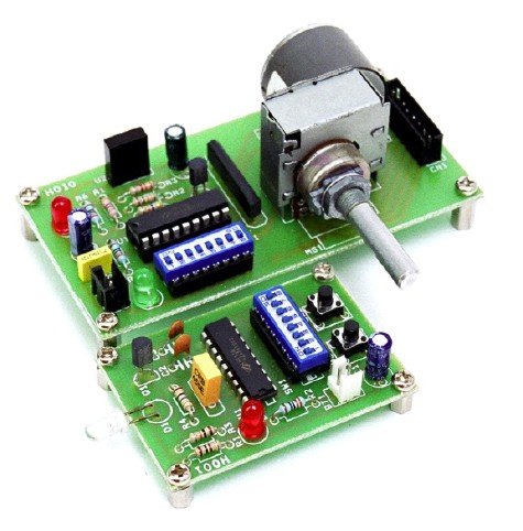
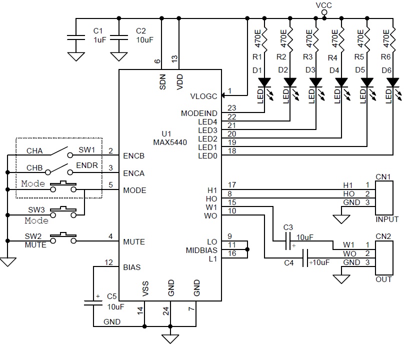
The project described here is a compact stereo volume and balance control with a rotary encoder. It provides 32 log potentiometer steps with buffered wiper output. The project can easily replace mechanical potentiometer. 5 LEDs indicate the volume level or balance settings , depending on the status of the mode indicator D1 LED. The
MAX5440 includes debounced pushbutton inputs for mute and mode. The mute input allows a single pushbutton to change between volume control and the -90dB (typ) mute setting. The mode input toggles between volume and balance control. A click-and-pop suppression feature minimizes the audible noise generated by wiper transitions.
MAX5440 DESCRIPTION
The
MAX5440 dual, 40kΩ logarithmic taper volume control features a debounced up/down interface for use with a simple rotary encoder without using a microcontroller (µC). Each potentiometer has 32 log-spaced tap points with a buffered wiper output and replaces mechanical potentiometers. An integrated bias generator provides the required ((VDD + VSS) / 2) bias voltage, eliminating the need for costly external op-amp circuits in unipolar audio applications. A mode-indicator LED output specifies volume or balance control. Five integrated LED drivers indicate volume level or balance settings, depending on the status of the mode indicator.
FEATURES
- Logarithmic Taper Volume Control with (31) 2dB Steps
- Low-Power Wiper Buffers Provide 0.003% THD
- Single +2.7V to +5.5V Supply Voltage Operation
- Low 0.5µA Shutdown Supply Current
- Integrated Bias Voltage Generator
- Five-Segment LED Volume/Balance Indicator
- Click less Switching
- 40kΩ End-to-End Fixed Resistance Value
- Mute Function Toggles to -90dB (typ)
- Power-On Reset to -12dBFS Wiper Position
SCHEMATIC
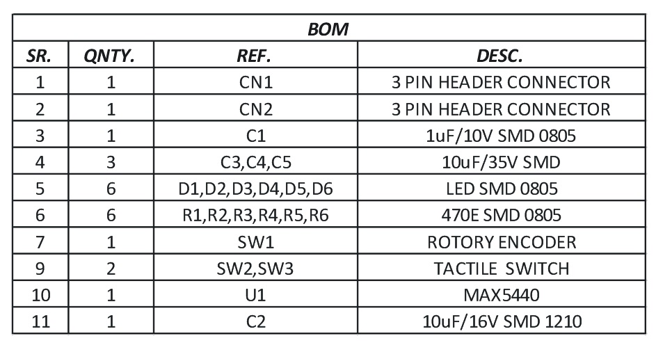
PARTS LIST
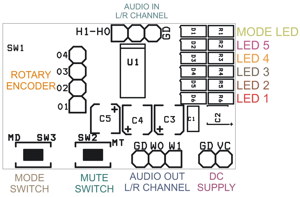
CONNECTIONS
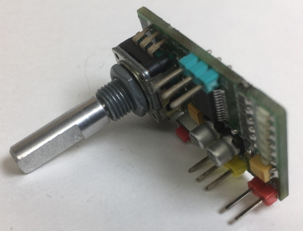
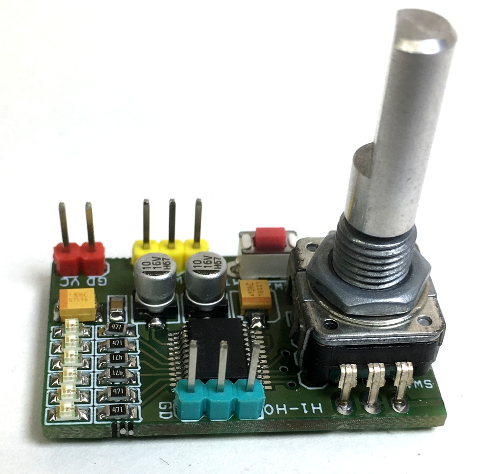
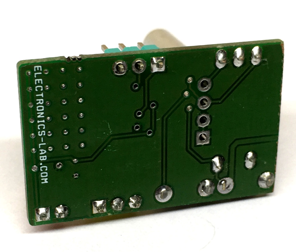
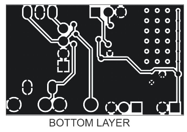
PHOTOS