


 >>>>>>>>>>
 Please note that these two schematics are independent.
 Download datasheet

Remote tester circuit also resembles the logic of a "dark sensor (using BC557)”. LDR has been replaced with IR sensor TSOP 1738. The circuit works as a remote tester. Pressing a remote control switch near the IR sensor, switches on the LED D2.
>>>>>>>>>>
Please note that these two schematics are independent.
Download datasheet
Explore more circuits, Arduino projects and practical electronics tutorials.
Discover more tutorials →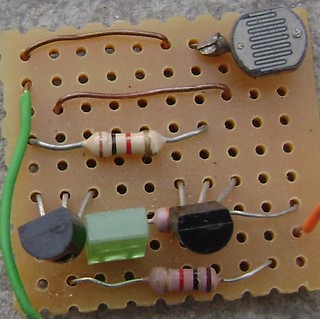
The circuit is ready for testing. Connect battery terminals and see the output. As you block light falling on...
Read tutorial ↗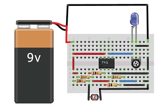
Explore this hands-on electronics tutorial.
Read tutorial ↗
Explore this hands-on electronics tutorial.
Read tutorial ↗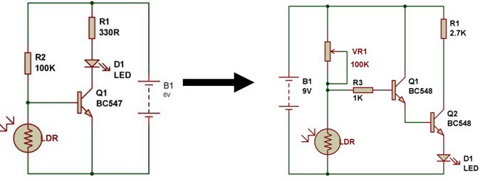
In this case, LDR has been replaced with capacitor C1-0.01uF and resistor R3-1K has been replaced with L1 & VC1. In...
Read tutorial ↗
For the circuit to work as light operated musical bell, we need to connect the SW1- switch to N/C terminal of relay....
Read tutorial ↗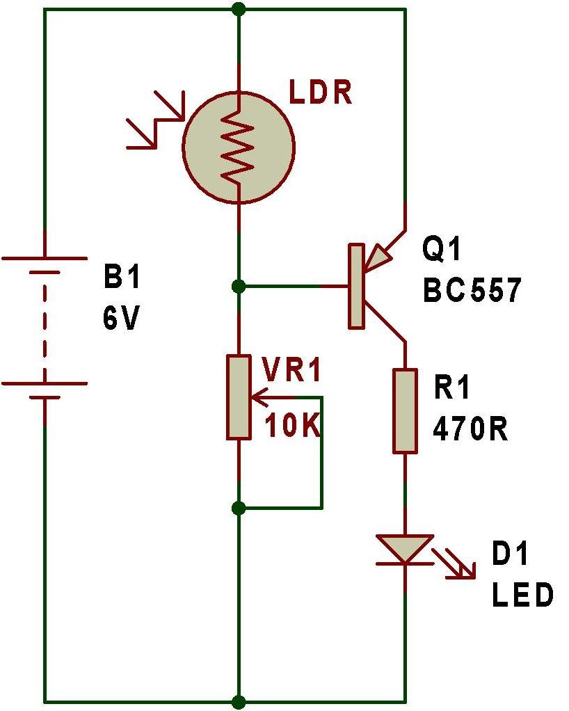
An automatic dark sensor can be made using a PNP transistor(BC557).
Read tutorial ↗