🛠️ Dive into our collection of DIY Kits, 🔊 Audio Amplifiers, Digital Scoreboards, FM transmitters, and more!
🎶 Explore endless possibilities at our new store.
MAKER TUTORIAL
Mode of NE555- Monostable
Monostable mode of operation
Monostable mode of operation of 555 IC can be explained using a simple touch sensitive circuit. Here, timing constant (T) of monostable timer= 1.1*R1*C1. The following circuit has been configured in monostable mode. A monostable circuit produces a single pulse(for a certain duration determined by the Timing Constant(T)=1.1*R1*C1) when triggered at pin 2.
BUILDCIRCUIT · 2010-11-12
⚡
Monostable mode of operation
Monostable mode of operation of 555 IC can be explained using a simple touch sensitive circuit. Here, timing constant (T) of monostable timer= 1.1*R1*C1. The following circuit has been configured in monostable mode. A monostable circuit produces a single pulse(for a certain duration determined by the Timing Constant(T)=1.1*R1*C1) when triggered at pin 2.
Touch sensor based on monostable mode of 555 Timer
Following circuit shows the working of Touch sensor. It operates in monostable mode. Here we can see resistor 100K and capacitor 100uF determine the monostable timing of the circuit. In place of touch plate, we can use a small piece of wire.Take a wire around 2-5cm long. Longer than 5cm may not work.
Timing(T)= 1.1*47K*100uF = 5.17 seconds
Dark sensor using 555(based on Monostable mode)
This circuit shows how we can convert a simple monostable mode circuit to “dark sensor”.We just need to add an LDR and a resistor in the circuit, then it simply works as dark detector.
When you block light falling on LDR, the circuit switches on the LED for a specific time determined by the values of R1 and C1.
Here, Timing(T)=1.1*47K*100uF = 5.17 seconds
You might have noticed that we can use the same components for making dark sensor as well as touch sensor.
Optimized Dark Sensor
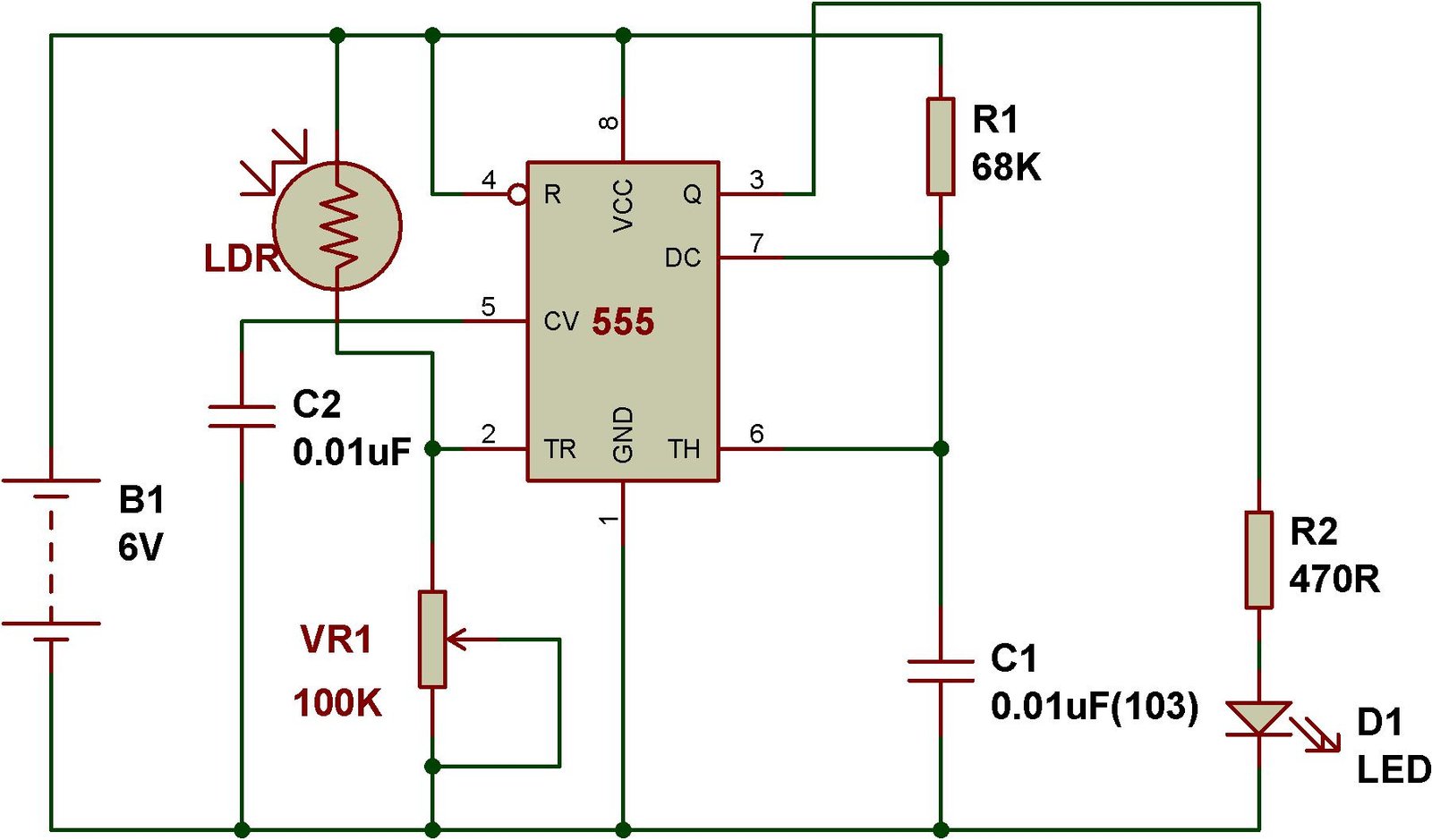
In place of R3-4.7K, if you use a variable resistor rated 100K, you can adjust the sensitivity of the circuit. Besides, use capacitor C1-0.01uF and resistor R1- 68K in place of 100uF and 100K respectively . That circuit would be better than the previous circuit.
Here, Timing(T)=1.1*68K*0.01uF = 0.000748 seconds. So, as soon as you let light fall on LDR, the LED- D1 switches off.
🛠️ Dive into our collection of DIY Kits, 🔊 Audio Amplifiers, Digital Scoreboards, FM transmitters, and more!
🎶 Explore endless possibilities at our new store.


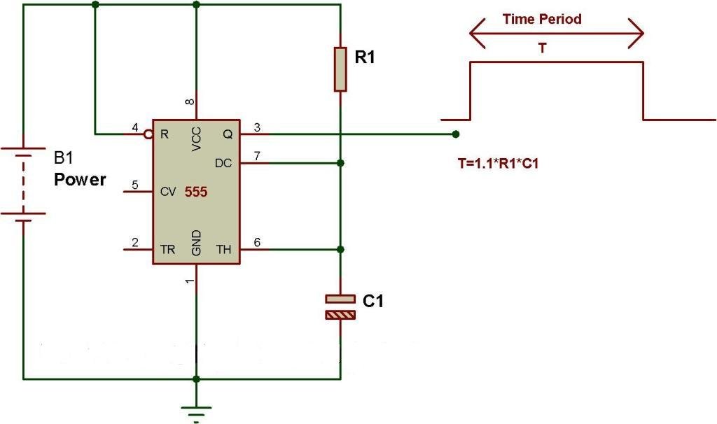 Touch sensor based on monostable mode of 555 Timer
Following circuit shows the working of Touch sensor. It operates in monostable mode. Here we can see resistor 100K and capacitor 100uF determine the monostable timing of the circuit. In place of touch plate, we can use a small piece of wire.Take a wire around 2-5cm long. Longer than 5cm may not work.
Timing(T)= 1.1*47K*100uF = 5.17 seconds
 Dark sensor using 555(based on Monostable mode)
This circuit shows how we can convert a simple monostable mode circuit to “dark sensor”.We just need to add an LDR and a resistor in the circuit, then it simply works as dark detector.
 When you block light falling on LDR, the circuit switches on the LED for a specific time determined by the values of R1 and C1.
Here, Timing(T)=1.1*47K*100uF = 5.17 seconds
You might have noticed that we can use the same components for making dark sensor as well as touch sensor.
 Here, Timing(T)=1.1*68K*0.01uF = 0.000748 seconds. So, as soon as you let light fall on LDR, the LED- D1 switches off.