MicroSD card breakout board for Arduino

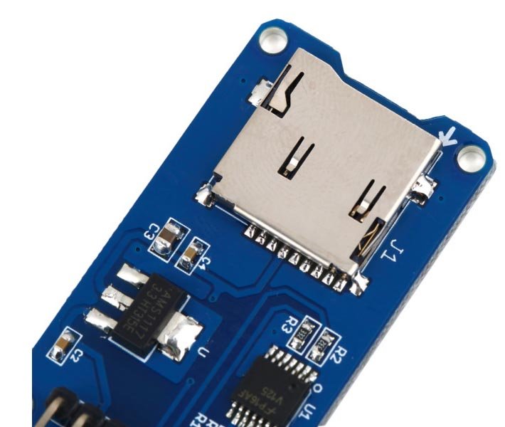
This is yet another MicroSD card breakout board for Arduino. Previously, we had released a similar MicroSD breakout board on our website. This module is bit cheaper than the previous one, that’s the only difference.
As we all know most of the microcontrollers have limited built-in storage. For example, Arduino UNO (Atmega328) has 1Kbytes of EEPROM storage and it might not be enough for all projects. If your project has any graphics, video, audio and data logging feature, you need a removal storage in it.
If you are working with some sort of data logging, graphics or audio, you will need at least a Megabyte of storage. In order to get that kind of storage, you need flash cards, or SD or microSD cards. These days, most of the micrSD cards come with minimum 2 gigabytes space in it. You can store data logging files on to your SD card and access the files using inbuilt SD card reader on your computer or using an external reader.
This module is available at buildcircuit.net.
Communication:
Communication with microSD cards is achieved over an SPI interface. The SCK, DI, and DO pins of the microSD socket are broken out to the ATmega168/328’s standard SPI pins (digital 11-13), while the CS pin is broken out to Arduino’s D10 pin. If you decide to use one of the many open source FAT libraries (like FAT16 or SDFat) make sure to change the code to reflect the location of the CS pin.
Read more about Serial Peripheral Interface(SPI)
Wiring
The breakout board comes with built-in ultra-low dropout regulator that converts voltages from 3.3V-6V down to ~3.3V. There’s also a level shifter that converts the interface logic from 3.3V -5V to 3.3V.
In this tutorial, we will be using an Arduino to demonstrate the wiring and interfacing. If you have another microcontroller, you’ll need to reconfigure the wiring.
Because SD cards require a lot of data transfer, they’re really good when connected up to the hardware SPI pins on a microcontroller. The hardware SPI pins are much faster than ‘bit-banging’ the interface code using another set of pins. For ‘classic’ Arduinos such as the Duemilanove/Diecimila/Uno those pins are digital 13 (SCK), 12 (MISO) and 11 (MOSI). You will also need a fourth pin for the ‘chip/slave select’ (CS) line. Traditionally this is pin 10 but you can actually use any pin you like. If you have a Mega, the pins are different! You’ll want to use digital 50 (MISO), 51 (MOSI), 52 (SCK), and for the CS line, the most common pin is 53 (CS). Again, you can change the CS (pin 10 or 53) later but for now, stick with those pins.
You can use the above configuration for testing the basic codes. For example, you can check the basic information about the MicroSD card.
Related Libraries:
- SD library- Available by default on the libraries folder when you download Arduino. Remember to change the CS=10. const int chipSelect = 10;
- Adafruit library– good for data logging references- Original link


