


MicroSD card breakout board – buildcircuit.com
Most of the microcontrollers have limited built-in storage. For example, Arduino UNO (Atmega328)has 1Kbytes of EEPROM storage and it might not be enough for all projects. If your project has any graphics, video, audio and data logging feature, you need a removal storage in it.
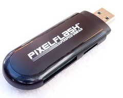
 If you are working with some sort of data logging, graphics or audio, you will need at least a Megabyte of storage. In order to get that kind of storage, you need flash cards, or SD or microSD cards. These days, most of the micrSD cards come with minimum 2 gigabytes space in it. You can store data logging files on to your SD card and access the files using inbuilt SD card reader on your computer or using an external reader.
Formatting notes:
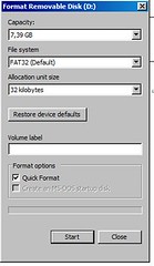
You can use your SD card without formatting, but it is also convenient to format it to a filesystem. The card must be formatted to FAT16 or FAT 32. You can use the SD card library for formatting or use general formatting procedure available in your operating system.
For example, I use Windows 7 and I format using the general procedure:
When you buy a SD card, there is chance that the card is pre-formatted with a FAT filesystem. The Arduino SD library we use supports both FAT16 and FAT32 filesystems. If you have a very small SD card, say 8-32 Megabytes you might find it is formatted FAT12 which is not supported. You need to reformat these cards. Whichever way you choose, its always good to format the card before using, even if it’s new. Note that formatting erases everything previously stored on your SD card, so, you better make a backup.
We strongly recommend you use the official SD card formatter utility – written by the SD association it solves many problems that come with bad formatting!
Download the formatter from https://www.sdcard.org/downloads/formatter_3/
Download it and run it on your computer, there’s also a manual linked from that page for use.
Wiring
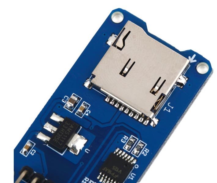
After formatting, your SD card is ready to use, we can simply wire up the microSD card into the breakout board.The breakout board comes with built-in ultra-low dropout regulator that converts voltages from 3.3V-6V down to ~3.3V. There’s also a level shifter that converts the interface logic from 3.3V -5V to 3.3V. Therefore, you can use the breakout board with 3.3V or 5V microcontrollers.
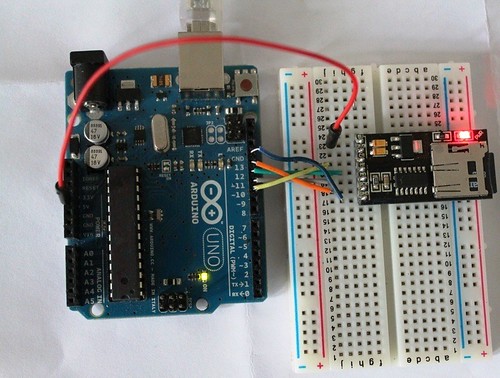
In this tutorial we will be using an Arduino to demonstrate the wiring and interfacing. If you have another microcontroller, you’ll need to reconfigure the wiring.
Because SD cards require a lot of data transfer, they’re really good when connected up to the hardware SPI pins on a microcontroller. The hardware SPI pins are much faster than ‘bit-banging’ the interface code using another set of pins. For ‘classic’ Arduinos such as the Duemilanove/Diecimila/Uno those pins are digital 13 (SCK), 12 (MISO) and 11 (MOSI). You will also need a fourth pin for the ‘chip/slave select’ (CS) line. Traditionally this is pin 10 but you can actually use any pin you like. If you have a Mega, the pins are different! You’ll want to use digital 50 (MISO), 51 (MOSI), 52 (SCK), and for the CS line, the most common pin is 53 (CS). Again, you can change the CS (pin 10 or 53) later but for now, stick with those pins.
Arduino Library & the First Experiment
Interfacing with an SD card is just easy, there is a library available, called SD.
Download the library by clicking the DOWNLOAD button at the top right. Then make a backup of the folder called SD in your ArduinoIDE/libraries folder (on a Mac you will have to ‘explore’ the App). Then uncompress the newly downloaded folder and rename it SD. Inside the SD folder you should see README.txt and other files. Install it by dragging it in your ArduinoIDE/libraries folder and restarting the IDE.
Next, select the CardInfo example sketch.
This sketch does not write any data to the card, but tells you if it managed to recognize it, and some information about it. This can be very useful when trying to figure out whether an SD card is supported.
Go to the beginning of the sketch and check if the chipSelect line is correct, for this wiring we’re using digital pin 10.
Then, insert the SD card into the breakout board and upload the sketch.
Open up the Serial Monitor and type in a character into the text box (& hit send) when prompted. You’ll probably get something like the following:
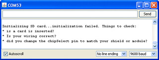
If you have not inserted the SD card or if there is something error in the hardware or connection, you will the following message:
Download
Transcend microSD card datasheet
Latest SD card library version from Adafruit – download it by clicking DOWNLOADS at the top right. Then make a backup of the folder called SD in your ArduinoIDE/libraries folder (on a Mac you will have to ‘explore’ the App). Then uncompress the newly downloaded folder and rename it SD. Inside the SD folder you should see README.txt and other files. Install it by dragging it in your ArduinoIDE/libraries folder and restart the IDE.
Other documents:
All photos of MicroSD card breakout board
Watch the following video:
🛠️ Dive into our collection of DIY Kits, 🔊 Audio Amplifiers, Digital Scoreboards, FM transmitters, and more!
🎶 Explore endless possibilities at our new store.


hello,can i ask…do you have the schematic circuit for arduino ? It is sold on an already soldered or the soldering my own ? tq 🙂 ASAP