DIY KIT 15- How to assemble infrared music transmitter and receiver DIY kit
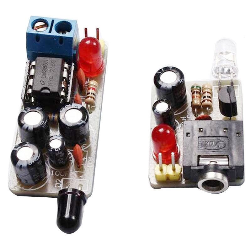
Assembling the infrared music transmitter and receiver kit is pretty straightforward. You can simply follow the silkscreen indicator and solder the components on its right spot.
The kit set includes a transmitter kit and a receiver kit.
Let’s start with the receiver first.
Speaker, battery connector/ battery holder and battery are not included. You need to buy them separately.
Components for receiver : Altogether 15 components including PCB
1. 2 x 0.1uF ceramic capacitor- Code 104
2. 1 x 0.22uF ceramic capacitor- Code 224- The PCB has 223 printed on it instead of 224. It is a mistake by the manufacturer.
3. 3 x 100uF/25V electrolytic capacitor
4. 1 x 10uF/25V electrolytic capacitor
5. 1 x 5mm LED
6. 1 x 1K Ohm resistor
7. 1 x 620K Ohm resistor
![]()
8. 1 x Phototransistor
9. 1 x LM386
10. 1 x IC header for LM386
11. 1 x Two pin screw terminal
12. 1 x PCB
How to assemble the receiver ?
The receiver is just an audio amplifier built with LM386. This is the PCB for receiver kit.
If you simply follow the silk screen labels you should be able to solder it easily.
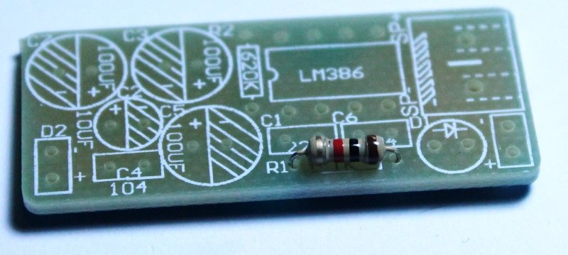
Step 1: Solder 1K resistor. The color code for 1K resistor is Brown, Black and Red.
Step 2: Solder 620K Ohm resistor
![]()
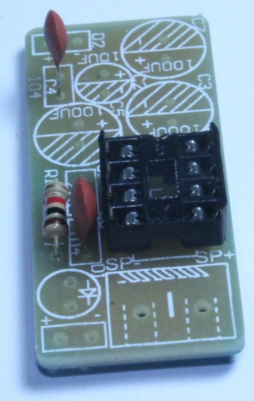
Step 3: Solder 2 ceramic capacitors marked as 104.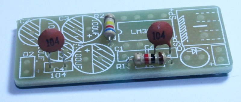
Step 4: Solder 8 pin DIL socket
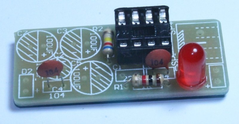
Step 5: Solder 5mm RED LED. The LED can come in other colors also.
The long(+) and short pin(-) of LED should go in the right hole.
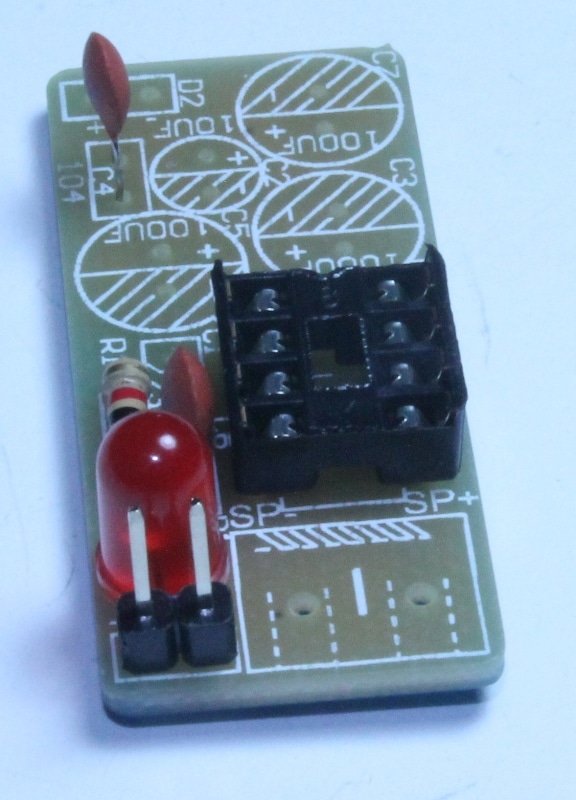
Step 6: Solder 2 pins male header. This is the point where you connect a 6V-9V battery.
You can choose to connect a 6V-9V battery connector straightaway without soldering the 2 pin header. The red wire of the battery connector goes to + and black wire goes to – .
Step 7: Solder 10uF capacitor. Be careful with the polarity of the capacitor. Insert the negative (-) side of the capacitor in the hole marked as – and insert the other pin to the hole marked +.
Step 8: Solder all the remaining remaining capacitors- 100uF at the right spot. Insert the negative (-) side of the capacitor in the hole marked as – and insert the other pin to the hole marked +.
Also solder the ceramic capacitor marked as 224.
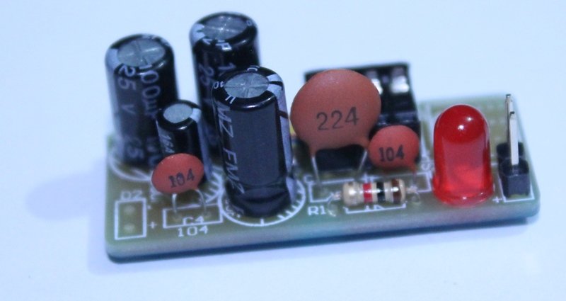
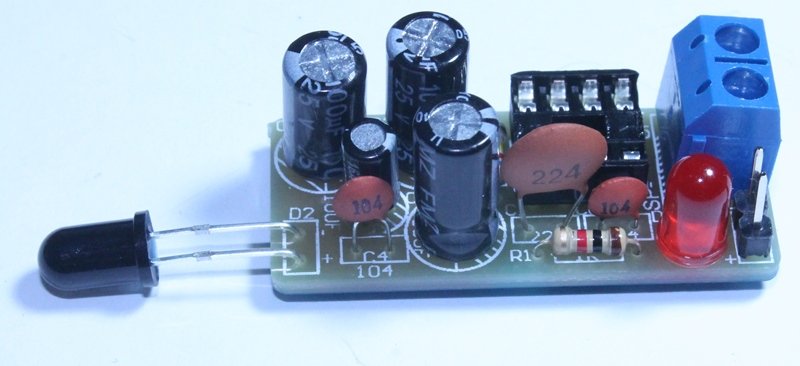
Step 9: Solder the black colored phototransistor. Connect the long pin at + and short pin at – . The long pin is Anode (+) and the short pin in cathode (-). Solder it exactly like it is shown on the image below.
Solder the Blue colored screw terminal on the PCB as shown on the image.
Step 10: Insert LM386 audio amplifier on the 2 pin DIL socket as shown on the image.
Step 11: Connect any 4 Ohm to 8 Ohm speaker to the 2 pin screw terminal
Step 12: Connect a 6V-9V battery connector as shown on the image. Red wire goes to + hole and black wire goes to – hole. It is optional thing. If you have a 6V battery connector, you can connect that. We chose to connect a 9V battery connector. You can connect any battery from 6V to 9V.
Your receiver kit is now ready. Look at the image below and see if it matches with your kit.
You can buy this kit at BuildCircuit Store
Related tutorials:


