Arduino programmer on breadboard using FT232RL
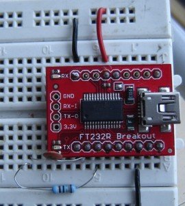
Before making an Arduino programmer on breadboard using FT232RL, you need to know about arduino, breadboard and USB to serial FT232RL break out board.
If you are an electronic novice, I recommend you to visit this page to get ideas on building simple electronic projects on breadboard.
You need following components for making an Arduino programmer:
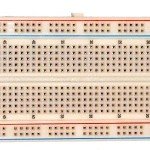
a. Breadboard
b. Reset or tactile switch
c. LED- any color
d. 330R, 10K, 100R resistors- 1/4 watt
e. 0.1uF, 22pF capacitors
 22pF capacitor has code 22.
f. 16Mhz crystal oscillator
g. USB to serial FT232RL breakout board
h. wires for connecting components
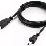
i. USB cable for connecting computer and FT232RL breakout board
You can see the picture below to get ideas for making an arduino programmer.
Picture made from Fritzing software and photoshop 7
You can use FT232RL break out board to program the microcontroller chip(ATMEGA328p). The RED LED kept on the board can be used to check if the circuit arrangement is able to program the chip.
About FT232RL breakout board (How is it connected to ATmega328p)
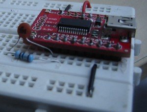
Place FT232RL breakout board on the breadboard as shown in the picture. If you flip over the FT232RL breakout board, you will the following pins names.
 This picture has been taken from www.arduino.cc
The breakout board has to be connected in the following way.
Note: you don’t need to connect external power source for operating this programmer because FT233RL breakout board itself draws power from computer.
Placing other components on breadboard
– One pin of reset switch goes to GND(ground) and the other pin goes to reset pin(Pin1 of chip).
– 10K resistor is connected across reset pin (Pin 1) and Vcc. Vcc is the power to run the programmer and that is drawn by FT232RL breakout board via computer.
– Pin 7 of chip goes to Vcc
– Pin 8 of chip goes to GND
– 16Mhz crystal oscillator is connected between Pin 9 and 10 of Atmega chip.
– One 22pF capacitor is connected across pin 9 and GND and the other capacitor across Pin 10 and GND.
– Pin 22 goes to GND
– Pin 20 and 21 go to Vcc.
– 330R resistor is connected to Pin 19 (DIG 13) and cathode terminal of LED and the led’s anode terminal is finally connected to GND.
See the pins of Atmega 328p
Final Look
Click on the picture to enlarge it
ATmega328 and 16×2 LCD connection-
Pin no. on Chip Pin no. on LCD
4 (DIG 2) 14
5(DIG 3) 13
6(DIG 4) 12
11(DIG 5) 11
12(DIG 6) 6
13(DIG 7) 4
Don’t forget to select the right COM port while uploading your code.
Other sources:









I found a dozen circuits for ATMega328. Half show pin 21 AREF floating and half have AREF to VCC. Which would be correct.
So basicly you can do this with any ECU ! But is there a way to do my c code in another program like MicroC and then compile …get a hex file and flash is with a program using FT232rl. I need a tool that writes that hex file in the controllers memmory using your configuration. Thanks:)
Hello, thanks for this, unfortunately I keep getting a not in sync error. Any ideas on how I can upload successfully?