Amarino Experiment- Sensor graph and LED controller- redirected
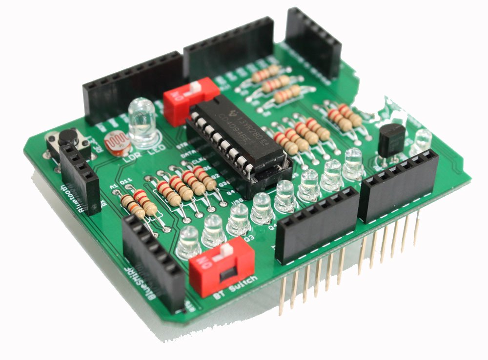
This experiment makes the use of ‘Android- Arduino BTCOMM Shield’ and Amarino. If you are not familiar with the shield, visit this page. This experiment is similar to my previous tutorials Sensor Graph basic experiment and Sensor graph and LED controller together.
If you have never worked with Amarino, I strongly recommend you to visit Amarino page and understand the basics of Amarino. In this experiment, the sensor signal from LDR is fed to A1. You can also see A1 clearly on PCB.
Get the circuit layout of Smart Phone- Arduino Shield
Steps:
a. Download Amarino and install on your Android Phone.
b. Download Amarino Library for Arduino and move it to the Libraries folder.
c. Download sensor graph(with LED controller) application and install on your phone. If you know Android Programming you can download the Android source code also. You can also get original Amarino source code, the original source code has only the Sensor Graph interface.
d. Download Arduino code and upload in your Arduino.
(Note: The Arduino sketch for this experiment is slightly different from the original source code from Amarino. The extra codes on the sketch deactivates the CD4094 chip. It is necessary to deactivate CD4094, otherwise, the power is shared with the chip and it affects this experiment. For Amarino 3.0 shield, you can simply switch off the DIP switch)
If you are interested in CD4094 experiments, follow this link.
NOTE: The Arduino Sketch has its baud rate set at 9600 bits/s. Therefore, your Bluetooth module should also have the same baud rate. Generally, the default baud rate of BlueSMiRF and general bluetooth adaptors is 9600 bps. However, if you want to change baud rate of BlueSMiRF module, follow this link. I have tested this experiment with both 57600 bps and 9600 bps and it works perfectly well. I don’t know if we can change baud rate of general ebay Bluetooth adaptors.
The shields version 1.0 and 2.0 have spaces for two different Bluetooth Adapters. Check if you have these adapters. Even if you don’t have these adapters, you can use any other by fixing on breadboard and connecting with extra cable.
If you buy Amarino shield version 3.0, there are headers for 3 different bluetooth adapters.
e. Stack your shield and Bluetooth adaptor over Arduino. Below you can see the connections for BlueSMiRF Mate Silver and general adapter.
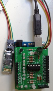
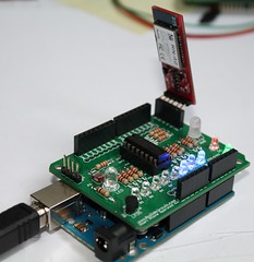
See photos for Amarino shield V.3.0.
f. Activate Bluetooth function of your phone and note down the MAC ID of your Bluetooth adaptor and write it on the text box of your application.
g. Connect to the Bluetooth adapter from your phone and operate the LED and see the LDR sensor’s response on the Amarino interface.
Note: The LED and LDR have been kept together so that LED light falls properly on the LDR and you can see the light sensor response clearly on the graph. If your room is highly illuminated, you can put piece of paper for better results.
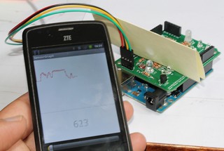
Fully assembled kit is also available on buildcircuit.net.
OTHER EXPERIMENTS WITH THIS SHIELD CIRCUIT LAYOUT ON BREADBOARD


