DIY KIT 44 – FM Transmitter DIY kit using 3 transistors
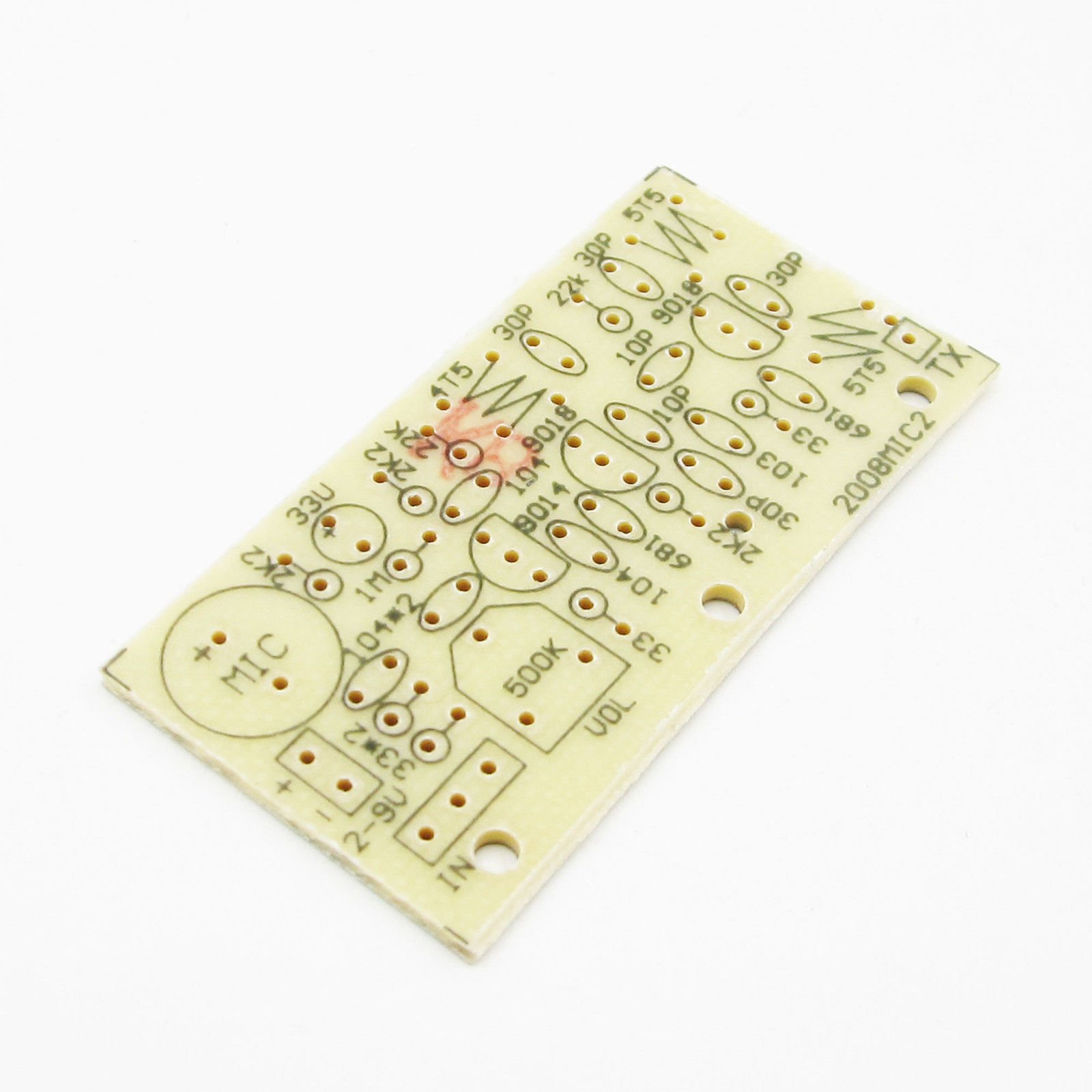
This is yet another FM transmitter DIY kit for beginners and hobbyists. It is slightly different from our previous FM transmitters. It has 3 NPN transistors and the transmission range is around 50-100 meters.
It is an enhanced wireless microphone with excellent transmission quality. The voice transmitted by the microphone can be heard using an ordinary FM radio. You can also transmit audio signals.
Frequency range: Around 83Mhz
Working voltage: 1.5V -9V
Range: More than 100 meters at 4.5V. For the general radio to receive the FM signal, users need to solder a 50cm wire to the kit.
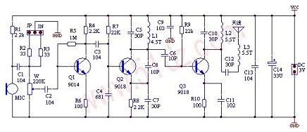
The following is the schematic and working principle:
The electret microphone converts the voice to an audio signal, the C2 works as a coupling capacitor sending the signals to the base of Q1. The signal received at Q1 is supposed to be modulated. When there is a sound signal, the transistor junction capacitance changes and it eventually changes the oscillation frequency which we can call ‘frequency modulation’ (FM).
FM signal is then fed to the high-frequency tuning amplifier via C6. The tuning amplifier amplifies the signal and then, C12 and L3, as well as the wire antenna transmits the signals as high-frequency electromagnetic waves.
- R1 is a bias resistance to electret microphone (MIC), generally selected in the range 2K-5.6K.
- R4 is the collector resistance.
- R5 is the base resistor, providing a bias current to Q1.
- R7, R8, C5, L1, C8, and C7 together form a high-frequency oscillation circuit.
- R7 to the Q2 base to provide bias resistance.
- C5 and L1 make the oscillation circuit.
- Q3, R9, R10, L2, C10, C11 constitute the high-frequency power amplifier circuit.
- C8 is the feedback capacitor to the transistor Q2.
- R8 works for the stability of the Q2 DC operating point.
- C7 is the capacitor for grounding distorted AC signals.
- R9 to the power transistor Q3 to provide the base current.
- C10 and L2 together work as a tuning circuit and the oscillation circuit C5 and L1 also tune at the same frequency to get the maximum output power so that the transmitter can transmit the electromagnetic signals as far as possible.
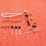
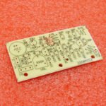
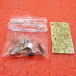
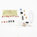
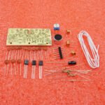
Check out the following images for assembly tips. You can see all the images on Flickr also.
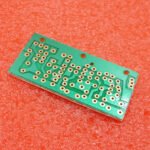
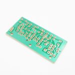
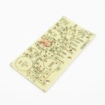
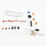
Check out the other images of the kit
One mistake: Step 1: There are 3 x 2.2K and 2 x 22K resistors. Not 5 x 2.2K resistors. Sorry for this mistake


