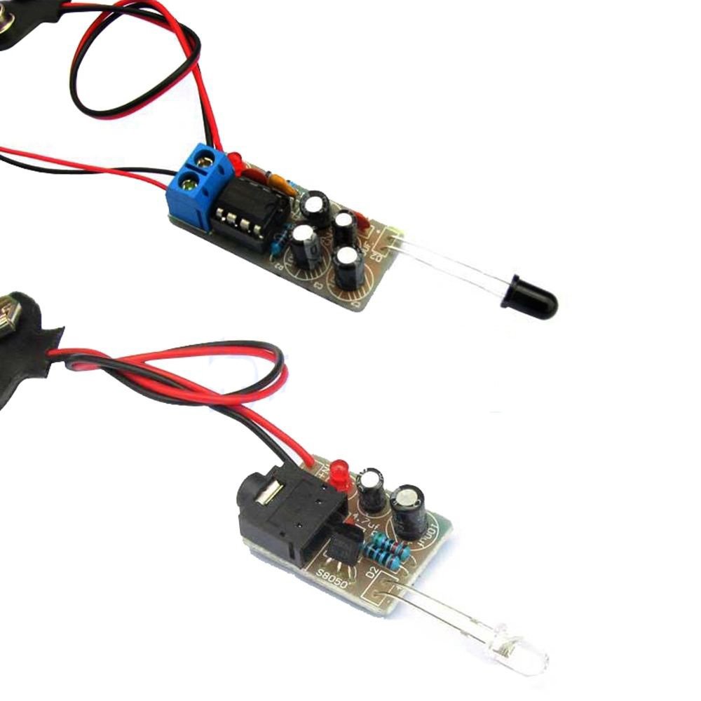
How to assemble infrared transmitter for infrared receiver DIY kit

Click here to go to assembly page of infrared receiver.
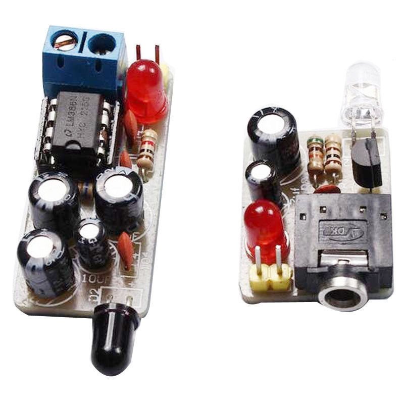
You will get these components with infrared transmitter kit:
- 1 x PCB
- 1 x Earphone Jack female
- 1 x Infrared LED
- 1 x 100uF electrolytic capacitor
- 1 x 4.7uF electrolytic capacitor
- 1 x S8050 transistor
- 1 x 5mm LED
- 1 x 0.01uF ceramic capacitor- Code: 103
- 1 x 100 Ohm resistor
- 1 x 51K Ohm resitor
![]()
Stereo jack is not included in this kit. You will need to buy it separately.
These are the steps for assembling infrared transmitter kit.
Step 1: Solder 100 Ohm and 51K Ohm resistors.
This is 51K
![]()
This is 100 Ohm

Step 2: Solder ceramic capacitor marked as 103.

Step 3: Solder the transistor S8050 as shown on the image below

Step 4: Solder the 5mm RED LED. Be careful with the anode and cathode pins. Insert the right pin in the right hole.
Step 5: Solder the stereo connector as shown below:


Step 6: Solder 4.7uF electrolytic capacitor as shown on the image below.
Be careful with the polarity of the capacitor. Insert the negative (-) side of the capacitor in the hole marked as – and insert the other pin in the hole marked +.

Step 7: Solder 100uF electrolytic capacitor

Step 8: Solder a 6V-9V battery connector to the holes marked as IN+ and IN-. The black wire of battery connector should go to IN- and the red wire should go to IN+.

Step 9: Solder the TRANSPARENT LED- the infrared LED to the spot marked as – and +. The long pin(anode) should go to + hole and short pin(cathode) should go to – hole.
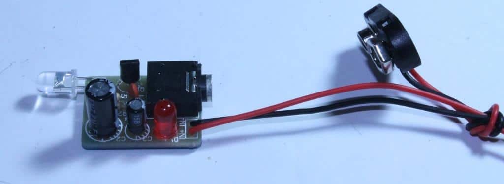
Battery connector and Infrared LED after assembly should look like as shown on the image below:
We have connected a 9V battery connector. You can also connect a 6V battery connector. It works for both.
Match your assembled kit with the shown below.
Use one end of your stereo jack to connect to your audio source, for example, mp3 player or mobile phone and the other end to the transmitter kit.
You can buy this kit at BuildCircuit Store
Related tutorials:


