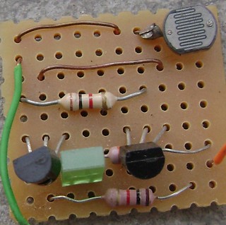
Dark sensor on breadboard
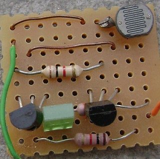
Get the following components:
NPN transistor- BC547 or BC147 or BC548
Resistor- 1K
Light emitting diode(LED)- Any color
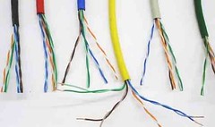
Connecting wires- Use single-core plastic-coated wire of 0.6mm diameter (the standard size)-You can use wire that is used for Computer Networking.
Power supply-6V or 9V
Components for this experiment are available at buildcircuit.net.
STEPS
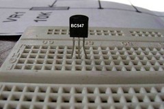
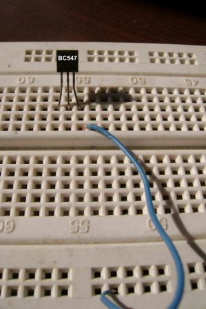
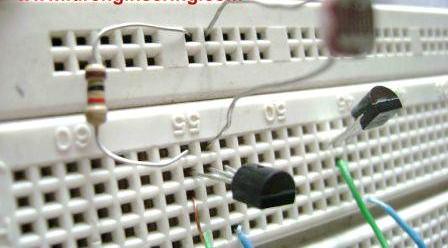
Step 1: Put first transistor Q1-BC547 on breadboard as shown in the picture.
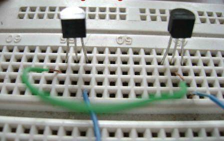
Step 2: Put another transistor Q2- BC547 on breadboard as in step 1.
Step 3: Put wires across emitter pin of both transistors and -ve terminal of battery(lowest/ bottom row of breadboard.)
Step 4: Put a wire across Collector pin of transistor Q1 and Base pin of transistor Q2.
Step 5: Put a resistor 1K across positive terminal of battery(topmost row of breadboard) and Collector pin of transistor Q1.
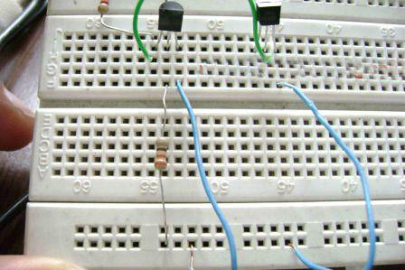
Step 6:Insert Light dependent resistor(LDR) across positive terminal of battery(topmost row of breadboard) and base terminal of transistor Q1.
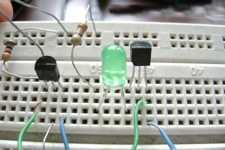
Step 7: Put a resistor- 330 Ohm across base pin of transistor Q1 and negative terminal of battery(lowest bottom row of breadboard).
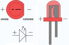
Step 8: Put a resistor 330R across positive terminal of battery(topmost row of breadboard)and anode terminal of LED(Light emitting diode) & Connect the cathode terminal of LED to Collector pin of transistor Q2.
The circuit is ready for testing. Connect battery terminals and see the output. As you block light falling on LDR(Light dependent resistor), the LED glows.
OUTPUT:
THIS CIRCUIT IS EXTREMELY SENSITIVE TO DARKNESS. EXPERIMENT THE CIRCUIT IN A HIGHLY ILLUMINATED ROOM.
LED GLOWS EVEN IN LESS DARKNESS. Use torch light if the LED glows in less darkness. You can adjust the sensitivity of the circuit using a variable resistor in place of R3-300 Ohm. Try this circuit with other resistances as well, for example, 1K, 10K and 100K, etc.
Components for this experiment are available at buildcircuit.net.






hi tell me the ratng of LDR ????
the rating of LDR is given here: http://uk.farnell.com/lprs/n5ac501085/light-dependent-resistor/dp/7482280
Actually, you can use any kind of LDR. this circuit works for any kind of ldr. best of luck.
Can any1 please briefly explain the workin of the curcuit
can i use 9v battery with same setup? please help!
YES. Please read others comments also.
hi.can u explain what is the different between LDR and Dark Sensor.it is same??
I want the reverse operation ie. Led ON if LDR is closed/dark … how to make it work with 5v supply …?