Assembly tutorial- FM transmitter DIY kit
If you have to come to this page directly from a search site, please go to this article first. This is the second article that gives assembly instructions for FM transmitter kit. Please click here for the first article.
In this article, we will see how to assemble the FM transmitter DIY kit.
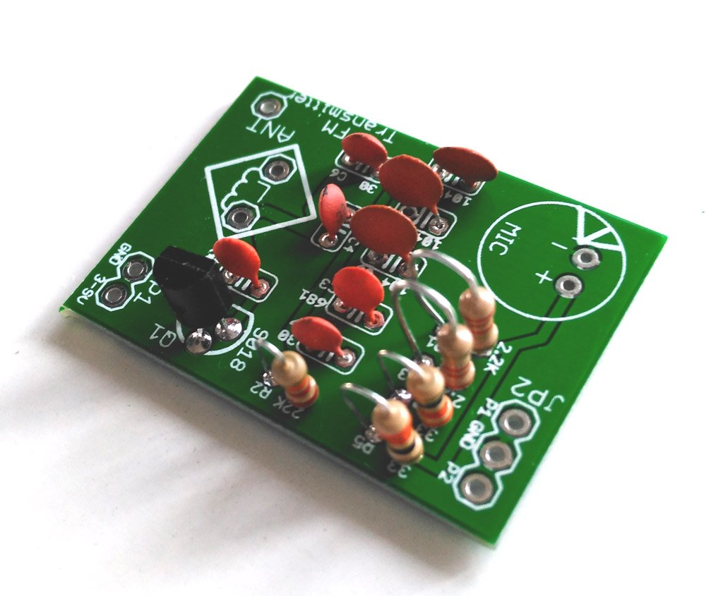
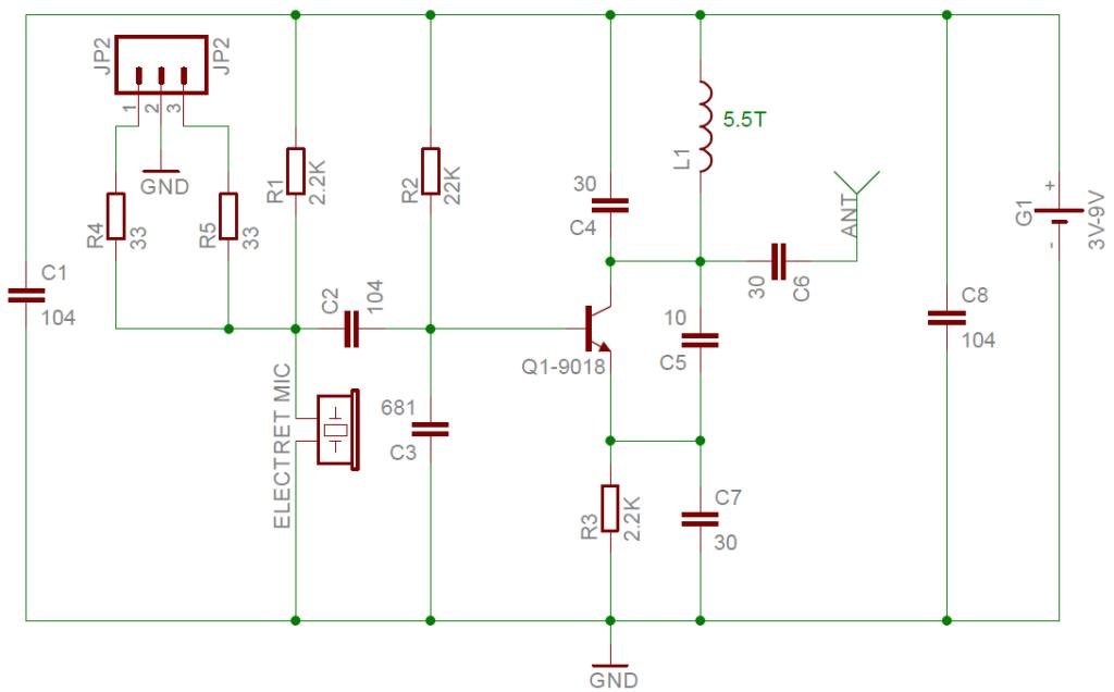
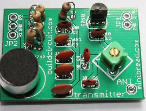
First of all, look at the schematic and PCB image given below.
If you closely look at the PCB and the schematic, you will notice that the pins on the PCB have been labeled clearly to make the assembly process easier. All the component values have been printed properly.
List of components required for the project:
- Electret microphone.
- Transistor(Q1)- S9018. Download S9018 datasheet
- R1- 2.2K
- R2- 22K or 18K. We will send both. With 18K and 35cm antenna, you can transmit audio signals up to 300-500 meters.
- R3- 2.2K (You can use 1K resistor in place of 2.2K. 1K transmits your voice up to 100 meters)
- R4- 33 Ohm
- R5- 33 Ohm
- C1- 0.1uF(Code- 104). Read here how to interpret capacitor code.
- C2- 0.1uF (Code- 104)
- C3- 680pF(Code- 681)
- C4- 30pF(Code- 30). This capacitor contributes to the FM transmission frequency.
- C5- 10pF(Code- 10)
- C6- 30pF(Code- 30). Coupling capacitor connected to the antenna of the kit.
- C7- 30pF(Code- 30)
- C8- 0.1uF(Code- 104)
- Inductor(L)- 0.1uH (5.5Turns coil). This contributes to the FM transmission frequency.
- G1- 3V-9V battery.
- Antenna- A short wire, 10cm-50cm long.
- Speaker jack(Optional). This is not that important, it is optional, you may use it to connect the transmitter directly to your music player. Read about it on this page.
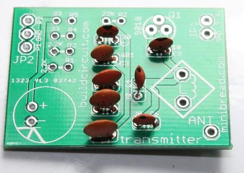
STEP 1: Start with ceramic capacitors. Fix all the capacitors on the board. Follow the labels of the components.
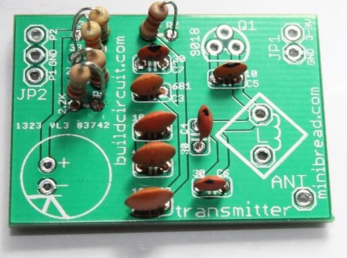
STEP 2: Fix all the resistors also. Please note that we will send 2.2K for resistor R3, but if you use 1K in place of 2.2K, the transmitter will transmit the audio signal up to 100 meters.
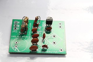
STEP 3: Fix transistor S9018. Download S9018 datasheet
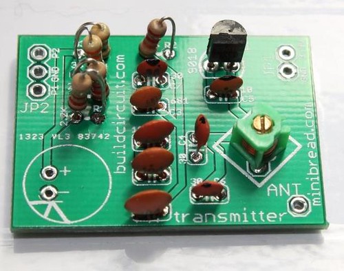
STEP 4: Fix the 5.5turns inductor coil
STEP 5: Fix electret microphone.
Please notice on the PCB that there is a mark with three lines(for negative pin) on microphone silkscreen. The mark has been made for making soldering process easier. If you look at real electret microphone, you can see similar solder mark. So, you just need to match that and solder the microphone.

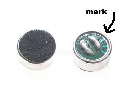 The solder mark connected to the case of electret microphone is negative pin.

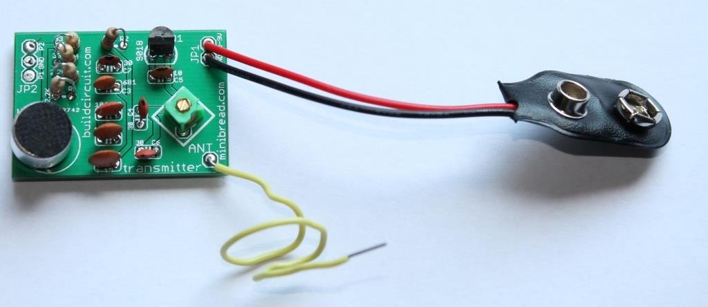
STEP 6: Fix antenna (ANT) and power supply connector. Use a wire for antenna, around 10cm-50cm long. The longer the antenna the farther the transmission. You may use 3V to 9V battery for the operating the kit.
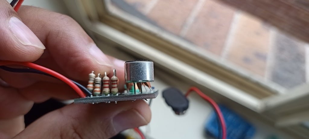 Longer antenna gives better transmission. The transmission range drastically increases. We are now sending 2pcs of 20cm wires. You can join them together and make longer antenna.
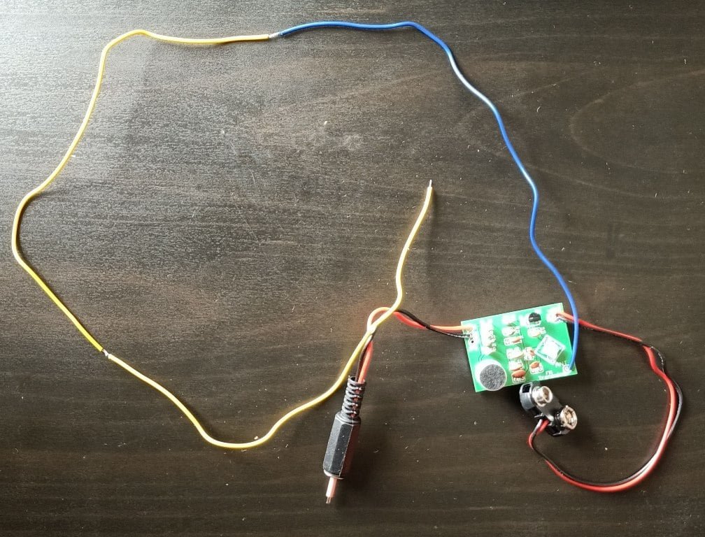
If you are willing to transmit music from your music player, you can connect a male speaker jack to JP2. On the image below, you can see how I have connected the jack on to the circuit board.
The black wire goes to GND and the red wire can be connected to P1 or P2.
This is how you should prepare the stereo jack for the transmitter. Click on the images to enlarge.
Testing of the kit:
Find an FM radio, turn on the power and volume, adjust the frequency around 88 MHz. Connect the kit to the power supply board, align towards the radio and use a screwdriver to adjust the oscillation coil L until the radio catches the signal. Then slowly increase the distance between the microphone and radio, while properly adjusting the radio (or handset) volume, tuning knob until the clearest sound is heard.
Important posts related to this article:
-
How to make this project on a stripboard- posted in March 2014.
- How to connect electret microphone.
- How to make an inductor coil for FM transmitter.
- How to make an FM transmitter- easy tutorial.
- Assembly tutorial for FM transmitter kit.
- Flickr images
- Video 1- Using electret microphone to pick up sound.
- Video 2- Using speaker jack to transmit sound. Transmit audio from your computer/music player.
- NEW ARTICLE- 10 factors that affect the transmission range of DIY FM Transmitters






can u build this circuit by using Proteus????actually i have taken your project as an example for my final year project..
can i use mono jack instead of stereo? when wiring the stereo jack, should the red wire be connected to the tip terminal or the ring terminal?
I make one but the frequency is not stable,and is when I touch the ganged capacitor the loudness increases pls what is the way out