Assembly instructions for Infrared transmitter module
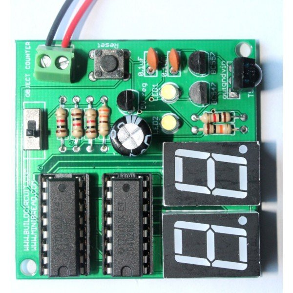
This article is about assembly of infrared transmitter used with digital object counter DIY kit. If you have come to this page directly from a search engine, please visit this page first to know about digital object counter. The suggested page gives you more details about this kit. You will eventually come back to this page, don’t worry 🙂 .
Check these articles for:
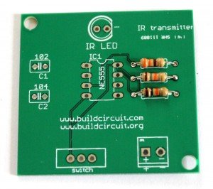
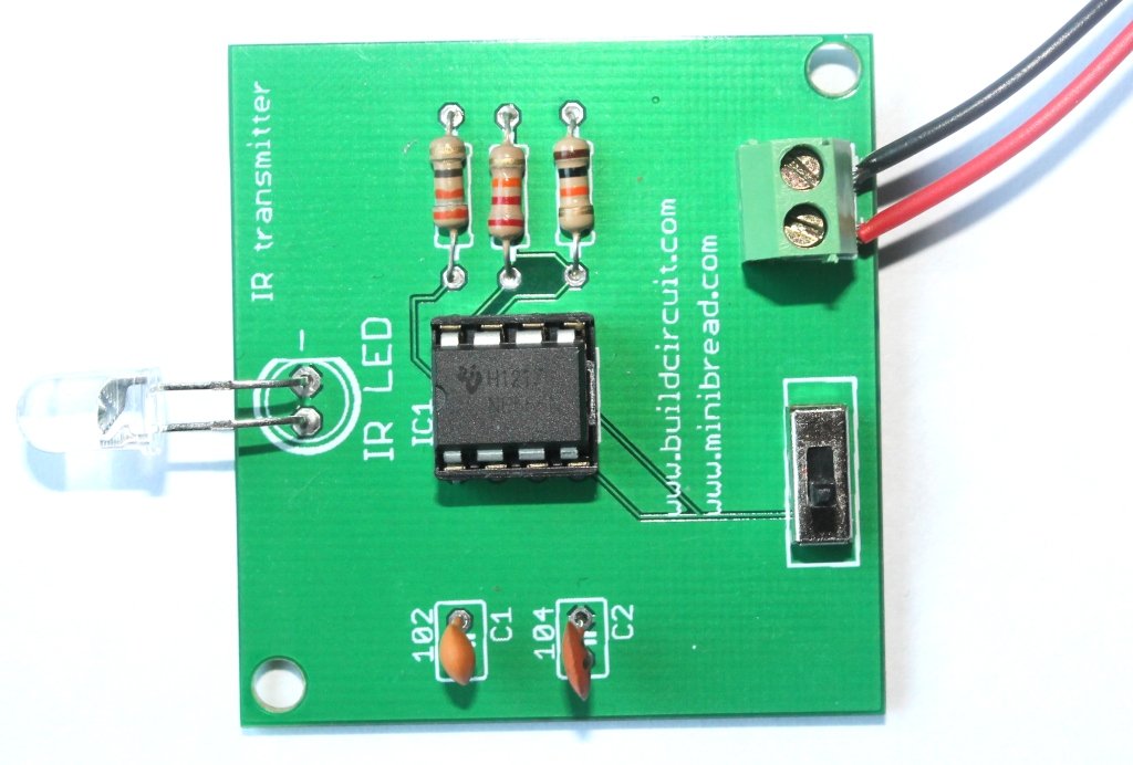
Assembly of IR transmitter kit is very straight forward and all components are through-hole. You can see the label and images printed on the circuit board and assemble the components accordingly.
Step 1: Fix resistors.
and R3: 330R-Orange-Orange-Brown-![]()
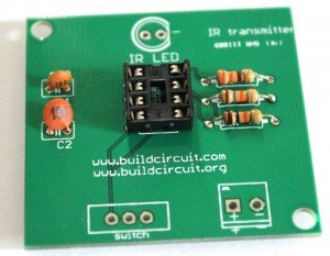
Step 2: Fix ceramic capacitors. Code for 0.1uF is 104 and code for 0.001uF is 102.
Step 3: Fix 8 pin IC socket. This socket is used for placing NE555 timer.
Step 4: Fix 2 pin screw terminal and SPDT switch. The screw terminal is used for connecting 6V-9V battery.
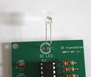
Step 5: Fix IR LED.
You can bend the IR LED as shown on the image below. This will give better performance. There is nothing hard and fast rule for this. The basic idea is that the IR LED and the IR receiver on the counter module should be in the line of sight(in a straight line).
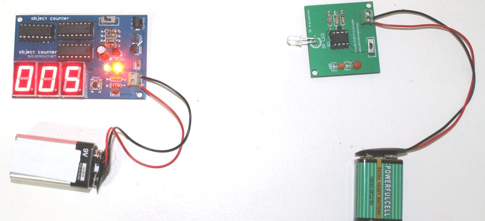
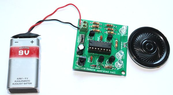
Your IR transmitter module is now ready. Connect a 9V battery on to the module and use it with the counter module. See on the image below how the battery is connected. Red wire is for positive and Black wire is for negative.
On the image below, you can see how the counter module and transmitter have been placed facing each other.
The following image shows how you place the 2 digit object counter and IR transmitter:
The following image shows how you to use a 3 digit digital object counter kit:
Other links:
- Assembly tutorial of 2 digit counter module
- Working of 2 digit object counter.
- Schematics of 2 digit object counter
- About 3 digit digital object counter kit


